


Airlock interlock multi-doors Interlocks Electronic Interlock for cleanroom
core principle of Airlock interlock
Airlock interlock use physical or logical means to make the opening/closing operations of valves interdependent and mutually restrictive. For example:
●Mechanical interlocks:
Use mechanical components such as levers, chains, or gears to connect the valve stems of two valves. When one valve operates, the mechanical structure forces the other valve to operate synchronously, ensuring the correct operating sequence.
●Electrical interlocks:
Achieve logical control through relays, contactors, or PLCs (Programmable Logic Controllers). For example, when a pressure sensor detects excessive pipeline pressure, the PLC outputs a signal to close the inlet valve and simultaneously open the exhaust valve to prevent system overpressure.
●Pneumatic interlocks:
Use compressed air pressure signals to control valve operation. For example, in pneumatic conveying systems for food processing, pneumatic interlocking devices ensure that materials are conveyed in sequence, preventing blockages or leaks.
core function of Airlock interlock
●Preventing Misoperation
Ensuring valves operate in the predetermined sequence prevents system malfunctions or accidents caused by incorrect operation. For example, in nuclear power equipment maintenance, key interlock devices prevent valves from being opened accidentally.
●Ensuring System Safety
In hazardous conditions (such as high pressure, high temperature, and flammable/explosive environments), interlock devices prevent valves from opening or closing simultaneously, avoiding system overpressure, leakage, or explosion. For example, DBB valves in LNG-fueled ships ensure emergency shut-off.
●Achieving Operation Sequence Control
Enforcing correct operating procedures ensures stable system operation. For example, in steam systems, condensate drain valves automatically open after the inlet valve is closed to prevent water hammer.
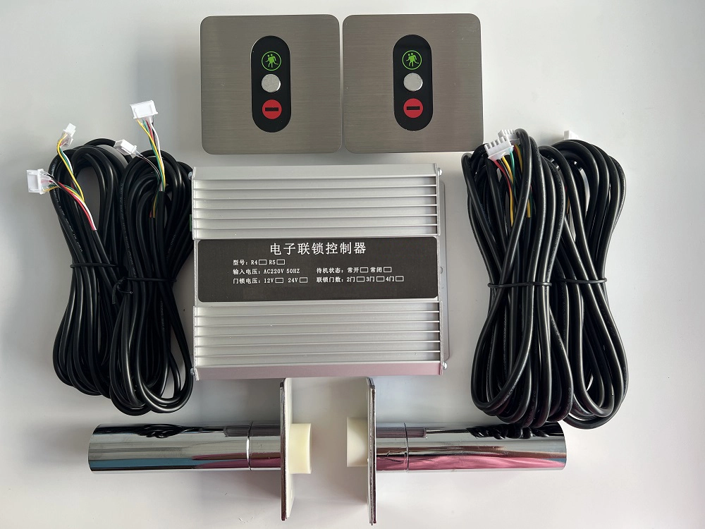
| Voltage | AC 220V 50HZ |
| Lock voltage | DC12V Door |
| magnetic type | Dry contact signal, door closed/closed |
| Specification | Main control board, indicator light panel, wiring harness, lock (determined based on the number of interlocked doors) |
| Functions | Type 86 button panel, interlock, alarm, emergency unlock, traffic light indicator, normally open and normally closed types available. |
| Note | The total power of the electric lock must not exceed 36W. |
Function Description
1. The system allows only one door (out of a maximum of eight) to be open at a time in the buffer zone. More than two doors can be opened simultaneously, and the interlocking logic can be configured.
2. If a door is left open, a continuous alarm will sound after 10 seconds.
3. In normal mode, the indicator lights on both sides of the door will be green, indicating the door is locked. The door can only be opened by pressing the open button on the panel. Closing the door will automatically lock it again.
4. A red indicator light indicates no passage; a green light indicates the door is unlocked.
5. In normal mode, pressing and holding the open button on the panel for more than 3 seconds will enter fire mode, unlocking all interconnected door locks. In fire mode, pressing and holding the open button on the panel for more than 3 seconds will return to normal mode.
6. The default door lock types in this system are electromagnetic locks and electric bolt locks.
FAQS